
Required Hardware
Pressure Line Leak Detection (PLLD)
|
Part Number |
Module |
|---|---|
|
0330374-001 |
Six-Input Pressurized Line Leak Interface Module |
|
0330843-001 |
Three-Output Pressurized Line Leak Controller Module |
|
0329359-001 |
Four-Relay Output Module |
Pump Sense
| Part Number | Module |
|---|---|
|
0329999-001 |
Four-Input Pump Sense Interface Module |
|
0329359-001 |
Four-Relay Output Module |
Wiring Setup
Pressure Line Leak Detection (PLLD)
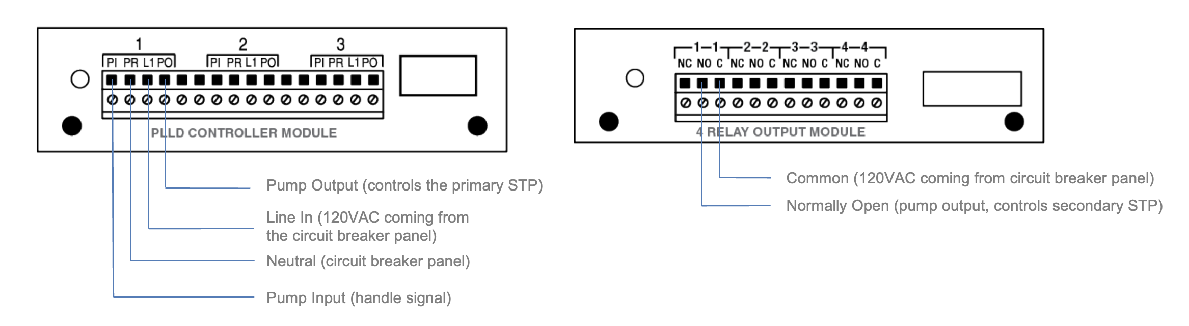
The primary STP - which holds the transducer - is controller by the PLLD Controller Module. The secondary STP is controlled by the 4 Relay Output Module.
PLLD Controller Module
- Pump Input (PI): handle signal, this will be 120VAC when the handle is lifted.
- Pump Return (PR): neutral, this should be wired to the breaker panel.
- Line In (L1): power in, this is always 120VAC and wired to the breaker panel.
- Pump Output (PO): this is wired to the primary STP’s control box, this will be 120VAC when the primary STP turns on.
4 Relay Output Module
- Common (C): power in, this is always 120VAC and is wired to the breaker panel.
- Normally Open (NO): pump output, this is wired to the secondary STP’s control box, this will be 120VAC when the secondary STP turns on.
- Normally Closed (NC): not used for this setup
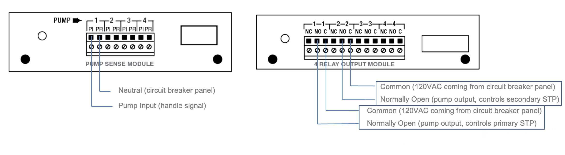
Pump Sense
Both STPs (primary and secondary) are controlled by the 4 Relay Output Module. Only one pump sense position should be wired and programmed to control the line manifold. Two relays are required, one per STP.
Pump Sense Module (1 position will be used for a line manifold)
- Pump Input (PI): handle signal, this will be 120VAC when the handle is lifted.
- Pump Return (PR): neutral, this should be wired to the breaker panel.
4 Relay Output Module (2 positions will be used for a line manifold)
- Common (C): power in, this is always 120VAC and is wired to the breaker panel.
- Normally Open (NO): pump output, this will be 120VAC when the STP turns on.
- Normally Closed (NC): not used for this setup
Programming
There are three steps involved in programming a line manifold system on a TLS-350 console:
- In-Tank Setup
- PLLD or Pump Sense
- Output Relays
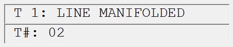
For the following steps, we will be using tanks 1 and 2. Tank 1 is primary, tank 2 is secondary.
|
Pressure Line Leak Detection: |
Pump Sense: |
|---|---|
|
In-Tank Setup: Line Manifolded: T1 must be manifolded to T2 |
In-Tank Setup: Line Manifolded: T1 must be manifolded to T2 |
|
PLLD: Select Tank: T1 (primary STP) Dispense Mode: see below for options |
Pump Sense: Select Tank: T1 (primary STP) Dispense Mode: see below for options |
|
Relay: Relay Type: Pump Control Output Select Orientation: Normally Open Select Tank: T2 (secondary STP) |
Two Relays must be programmed:
R1: Relay Type: Pump Control Output Select Orientation: Normally Open Select Tank: T1 (primary STP)
R2: Relay Type: Pump Control Output Select Orientation: Normally Open Select Tank: T2 (secondary STP) |

Dispense Mode Options:
- Standard – Only one pump feeds the line (not used in a line manifold setup)
- Manifold Alternate (volume) – The console will run the tank with the greatest inventory volume
- Manifold Alternate HT (height) – The console will run the tank with the greatest inventory height.
Note: Only available in software version 134 or higher
- Manifold Sequential – The tanks are pumped low one at a time. When the tank’s volume drops below the entered Pump Threshold percentage, pumping will switch over immediately to the next available tank in the line manifolded set.
- Manifold All Pumps – All pumps turn on at the same time
Further Information:
- Contact Veeder-Root Technical Support at 1-800-323-1799 for additional help or questions.
- Learn more about Veeder Root Products on our webpage.
- Technical Support Notification - TLS-350 Line Manifold Setup _ Programming (576047-397).pdf