Overview
The following technical service notification discusses considerations for troubleshooting Digital Pressurized Line Leak Detection (DPLLD) Communication Alarms with Variable Frequency Controllers. Only certified contractors should install or service Veeder-Root products. Download Technical Service Notification - Troubleshooting DPLLD Comm Alarms with Variable Frequency Controllers (576047-333).
There are many factors to consider when troubleshooting DPLLD Comm Alarms – site conditions, variable frequency controllers, incorrect wiring, bad transducers and other external electrical devices. The checklist below is intended to be used in conjunction with product manuals. For more information, visit our Technical Document Library.
Troubleshooting Tips
Transducer Wiring
The transducer wiring is classified as Intrinsically Safe (IS), which means that it uses low energy. Mixing high and low voltage wiring is a cause of electrical noise interference and a safety issue. Verify the following:
- The transducer is wired to the console using shielded cable with stranded wire. The shields must be grounded in the console but not in the sump.
- Ensure that no IS wiring is sharing conduits, wiring troughs or electrical boxes with high voltage wiring or wiring from any other system.
Grounding
Grounding is important because it helps prevent electrical noise interference. When two devices do not share the same ground source, this too can be a cause of electrical noise interference. Check for the following:
- Confirm the site has a good grounding source, such as a ground rod.
- Confirm the console, other devices associated with the console and STPs are properly grounded and share the same ground point.
- The console must have two isolated grounds.
- Disconnect the ground wires from the console and place the leads of an ohm meter on each wire. Confirm there is less than 1 ohm of resistance between the two wires. If there is greater than 1 ohm, look for damaged wires or incorrect grounding.
Diagnostics
On the Veeder-Root TLS-450PLUS console, go to Menu → Diagnostics → LPR Sensors.
- Record samples read and samples used. If possible, compare these numbers to a good transducer.
- In an ideal situation, the samples read vs. samples used will match, but a small difference is acceptable. Look for any large disparities, this is an indication of a communication problem. (This will help you identify the problem and let you know that the issue has been resolved.)
- Record Parity Errors, Partial Reads or Communication Errors.
Submersible Turbine Pump (STP) Wiring
- Verify all STPs are wired according to manufacturer specifications.
- The DPLLD transducer has a metal to metal contact with the STP. Verify the ATG and the STP share the same ground point. Having more than one ground can cause electrical noise interference.
Other Factors to Consider
Are all the lines going into alarm or just one?
- If only one line is going into a DPLLD Comm Alarm, then the issue could be caused by a bad transducer or another device on this line. Start by swapping transducers with another line. If the issue follows the transducer, replace it.
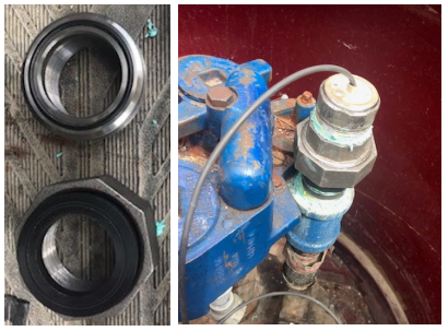
- If the issue stays on this line, or all lines are going into alarm, installing a dielectric union will help isolate the transducer. Dielectric unions help isolate the transducer from the STP and can reduce or eliminate DPLLD comm alarms. Dielectric unions can be found at plumbing supply stores.
Is the Comm Alarm activating at a specific time each day?
- Alarms may be triggered by devices that turn on at the same time every day, such as canopy lights.
- Once the device is found, try to duplicate the problem.
- LED lighting, neon signs and refrigeration units are known as a cause of electrical noise interference.
If all DPLLD lines are going into the Comm Alarms, then this issue could be caused by the ATG or wiring.
- Check the console’s grounding. Make sure the console has two isolated grounds. For variable speed STPs, confirm that a 3-phase motor is installed.
- Check the motor windings and refer to the manufacturer’s service manual for correct ohm readings. On a 3-phase ump, the ohm reading will be the same on all three legs.
Note: There should also be no capacitor on a 3-phase motor.
Further Information
- Contact Veeder-Root Technical Support at 1-800-323-1799 for additional help or questions.
- Learn more about the Electronic Pressurized Line Leak Detection (PLLD) System.
- Technical Service Notification - Troubleshooting DPLLD Comm Alarms with Variable Frequency Controllers (576047-333)