
Wiring Setup
DPLLD Transducer
• Each transducer is wired to the USM Module.
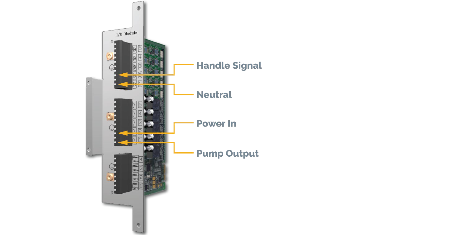
Relay (Pump Control Output)
• One terminal is the power in, this is always 120VAC and wired to the breaker panel.
• The other terminal is wired to the pump control box, this will be 120VAC when the pump turns on.
External Input (Pump Sense)
• One terminal is wired to the handle signal. This will be 120VAC when the handle is lifted.
• The other terminal is the neutral, this should be wired to the breaker panel.
Programming Steps
Below is a brief list showing the order in which PLLD must be programmed.
WARNING: Not going in order will cause the console to go into multiple setup data warnings.
1. Devices
a. Relay
b. External Input
c. Line Pressure Sensor
2. Pumps and Lines
a. Pumps
b. Lines
c. PLLD
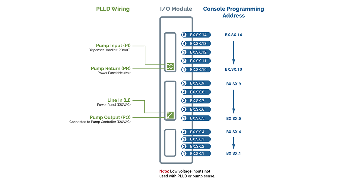
I/O Module Addressing
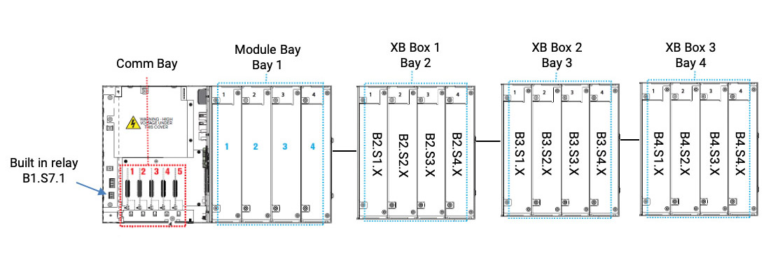
ATG and Expansion Box Addressing
Device Setup
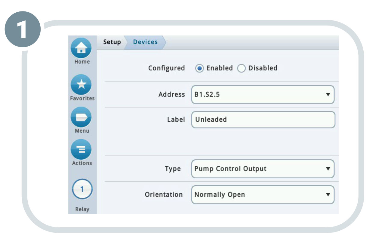
1. Relay
a. Configured: Enabled
b. Select Address: BX.SX.5-BX.SX.9
c. Enter a Label (fuel type): Ex: Unleaded, Premium, Diesel
d. Type: Pump Control Output
e. Orientation: Normally Open
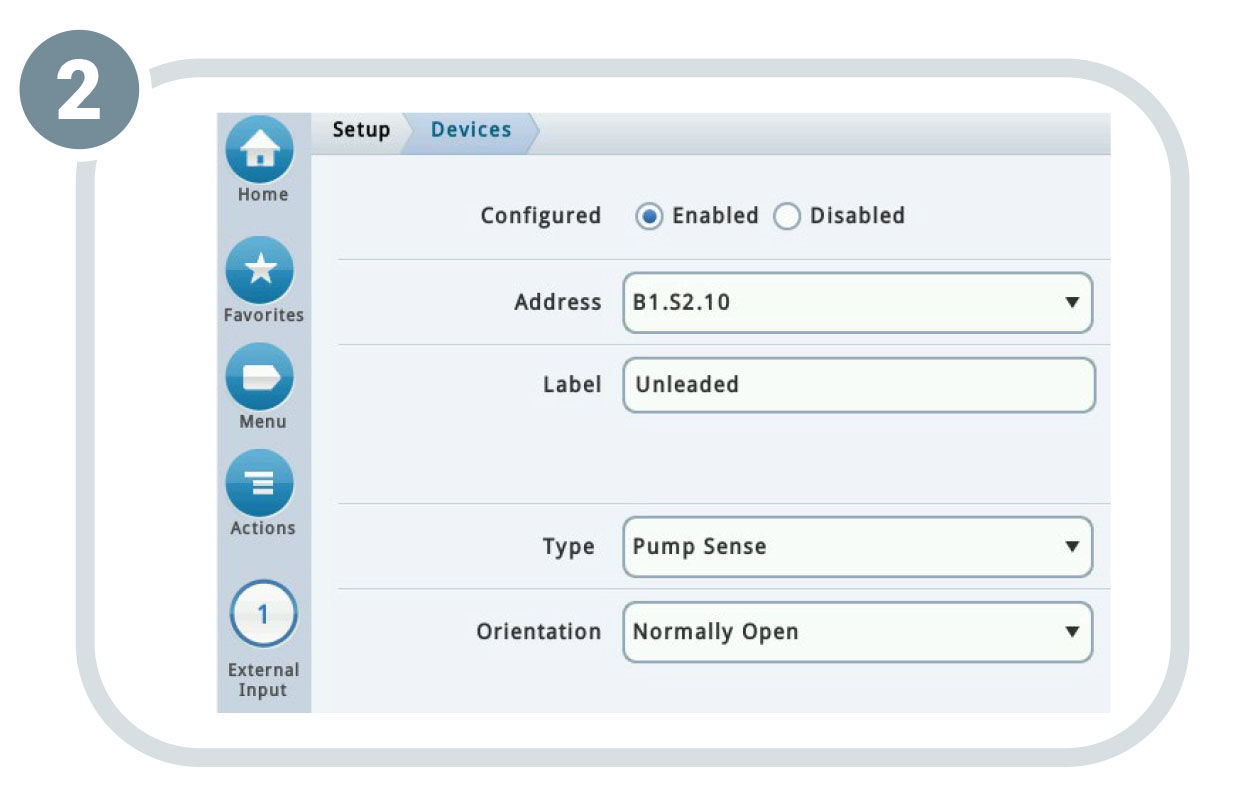
2. External Input
a. Configured: Enabled
b. Select Address: BX.SX.10-BX.SX.14
c. Enter a Label (fuel type): Ex: Unleaded, Premium, Diesel
d. Type: Pump Sense
e. Orientation: Normally Open
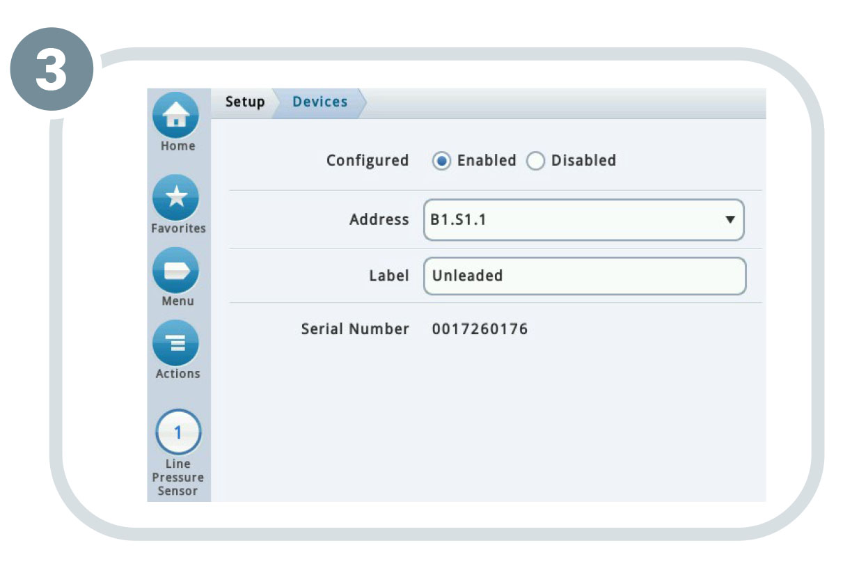
3. LPR Sensor
a. Configured: Enabled
b. Select Address on USM
c. Enter a Label (fuel type): Ex: Unleaded, Premium, Diesel
d. Once saved, the serial number will appear
Pumps and Lines Setup
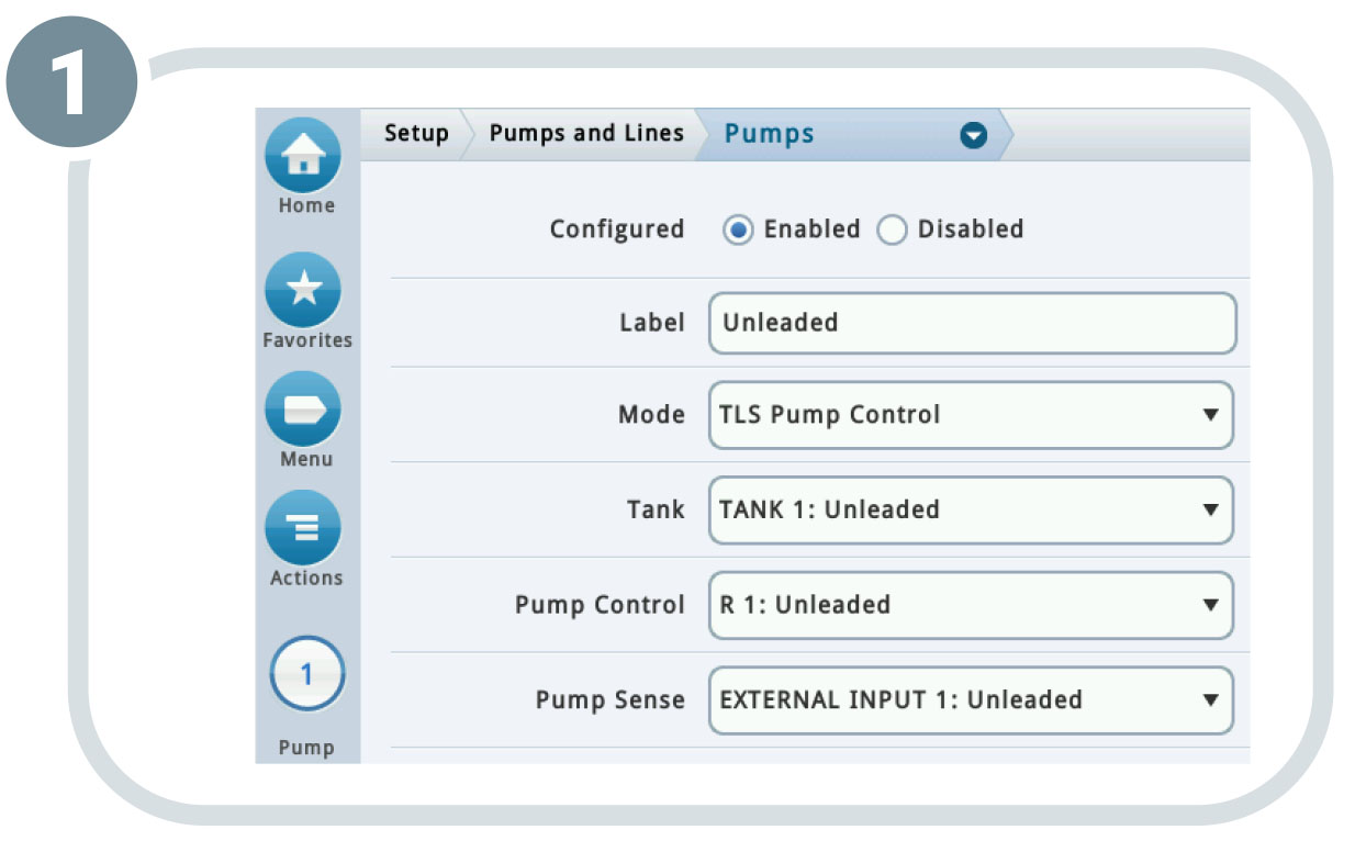
1. Pump
a. Configured: Enabled
b. Enter a Label (fuel type): Ex: Unleaded, Premium, Diesel
c. Mode: TLS Pump Control
d. Tank: Select a tank
e. Pump Control: Select a relay
f. Pump Sense: Select an external input
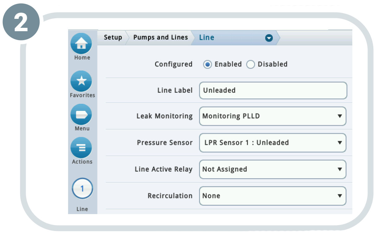
2. Line
a. Configured: Enabled
b. Enter a Label (fuel type): Ex: Unleaded, Premium, Diesel
c. Leak Monitoring: PLLD
d. Pressure Sensor: Select a LPR sensor
e. Line Active Relay –Not required
f. Recirculation–Not required for PLLD – for use with DEF Recirculation
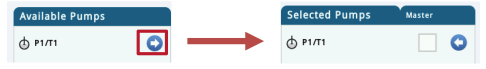
g. Selected Pumps (scroll down):
- Use the arrows to select the desired Pump
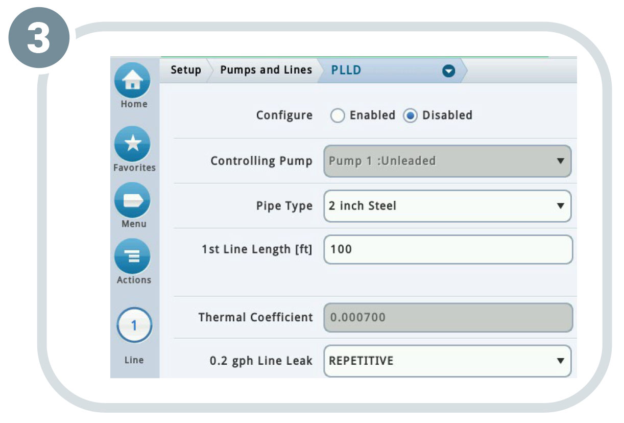
3. PLLD
a. Configured: Enabled
b. Select Pipe Type
c. Enter Line (Piping) Length
d. Set the following per customer or local regulation requirements:
- 0.2 gph Line Leak
- 0.1 gph Line Leak
- Shutdown Rate
- Low Pressure Shutoff
- Low Pressure Alarm Limit
- Continuous Handle Timeout
- Fuel Out Limit
e. Pump Comm Control Relay: Not required
4. Perform a manual gross test to enable the line
Further Information
- Contact Veeder-Root Technical Support at 1-800-323-1799 for additional help or questions.
- Learn more about pressurized line leak detection products.