Home
Header Top Menu
  • Financing Bundle
  • Blog
  • Contact
  • Distributor Locator
  • Service Locator

Main navigation

  • Fueling Solutions
    • Solutions
      • Combat Corrosion
      • Leak Detection Methods
      • Integrated DEF Management System
      • Fleet Fuel Management System
      • Solutions for Bulk Fuelers
      • Automate Processes in Aviation Fueling
      • What happens when you fuel up at a gas station?
    • Product Guides
      • HydrX System Configurator
      • STP Selection Guide
      • Probe & Float Kit Selection Guide
      • Sensor Selection Guide
  • Products
    • Automatic Tank Gauges (ATGs)
      • TLS-450PLUS Automatic Tank Gauge
      • Upgrade to the TLS-450PLUS Automatic Tank Gauge
      • In-Station Diagnostics
      • TLS4 & TLS4B Automatic Tank Gauges
      • Stainless Steel Probes & Float Kits
      • Leak Detection & Monitoring Sensors
      • Remote Connectivity
      • Tank Monitoring Accessories
    • Red Jacket Submersible Pumping Systems
      • The Red Jacket 4" Pumps
      • The Red Jacket 4 HP Submersible Turbine Pump
      • The Red Jacket Manifolded Submersible Turbine Pumping System
      • Red Jacket Diagnostic Monitoring
      • CoreDEF™ Submersible Turbine Pumps
      • Pump Control Boxes
      • The Red Jacket STP Accessories
    • HydrX Fuel Conditioning System
    • Additive Injection System
    • Biofuel Blending System
    • Biofuel Injection System
    • Meter Registers
      • Electronic Meter Register Products
      • Mechanical Meter Registers & Dispenser Computers
  • Support
    • Contact Technical Support
    • Warranty & Order Support
    • Insite360 Support
    • Software Downloads
    • Technical Document Library
    • Product Submittal Documents
    • Obsoleted Product Notifications
    • Technical Support Notifications
    • Software Release Notifications
    • Certified Technician Training
    • Tutorials & Operator Tips
      • TLS-450PLUS Operator Tips
      • Web-Enabled Interface Tips
      • TLS-350 Operator Tips
      • CDM Tutorials
      • CDM Advanced Tutorials
  • About
    • Company Overview
      • Our Parent: Vontier
      • Our Culture
    • Careers
      • Current Openings
      • Benefits
      • Careers in Operations
      • Careers in Technology
      • Students and Recent Graduates
    • Global Locations
Language Switcher
  • North America
  • Latin America
  • Europe
  • Nordic
  • Middle East and Africa
  • Brazil
  • India
  • China
  • South East Asia
  • Australia
Sidebar Menu
  • Find a Distributor
  • Get a Quote

Get a Quote

Find a distributor near you

Enter your city, state, or postal code
  • Home
  • Intelligent Pump Control Installation Checklist

Intelligent Pump Control Installation Checklist

Veeder-RootSeptember 26, 2022Technical Support, Red Jacket
Share

Introduction

This checklist is specific to Intelligent Pump Control (IPC) with Red Jacket IQ Control Boxes. It will provide Technicians and Owners with the documentation that IPC has been installed correctly.

IPC Installation Checklist

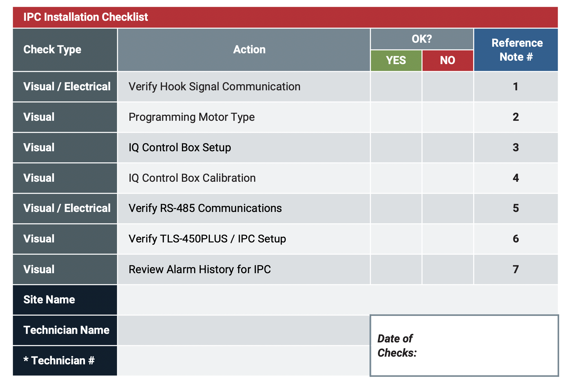
* Your Technician # can be found on your Red Jacket Foundation Certificate.

Note: This checklist should be used in conjunction with the IQ Control Box Installation and Owner’s Manual (051-330).

Guidance Notes for Red Jacket IPC Installation Check

Note 1 – VERIFY HOOK SIGNAL COMMUNICATION

  • Verify each product's hook signal is being read by the TLS-450PLUS Automatic Tank Gauge (ATG)
    • PLLD Diagnostics Screen
    • Verify Voltage from D2 to GND inside IQ Control Box (should be ~120V)
      • If no Power, Check Circuit breaker panel and verify TLS Relay assignment is correct per product
Verify Hook Signal Communication

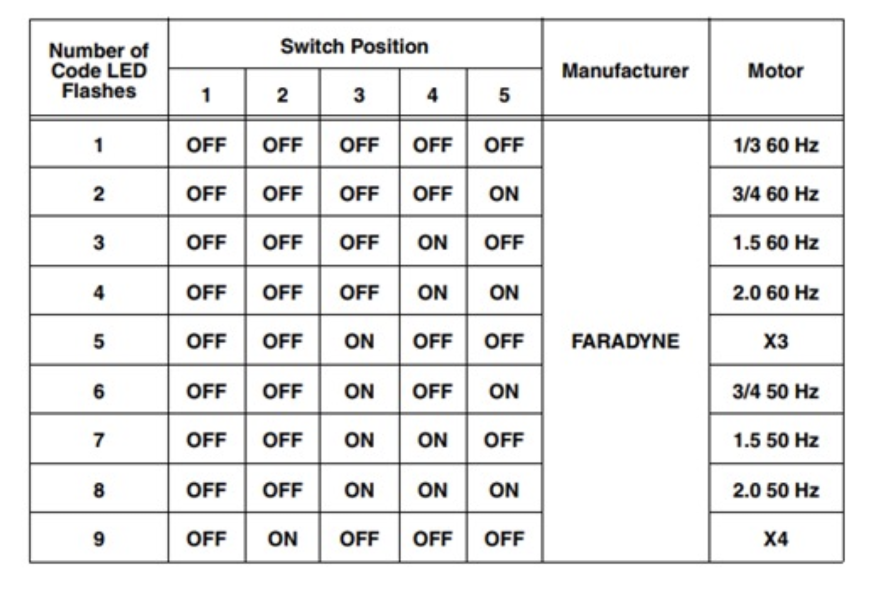
Note 2 – PROGRAMMING MOTOR TYPE

  • Ensure Programming Motor Type done correctly in IQ Control Box by number of green flashes matching Table 5 or Table A-3 (Manual No: 051-330)
    • Also, to the right:
Programming Motor Type


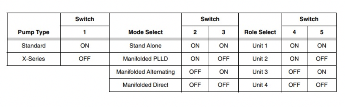
Note 3 – IQ CONTROL BOX SETUP

  • Verify IQ Control Box Setup Switch (SW1) matches desired pumping expected configuration from Table 7 or Figure A-5 (Manual No: 051-330)
    • Also, to the right:
IQ Control Box Setup

Note 4 – IQ CONTROL BOX CALIBRATION
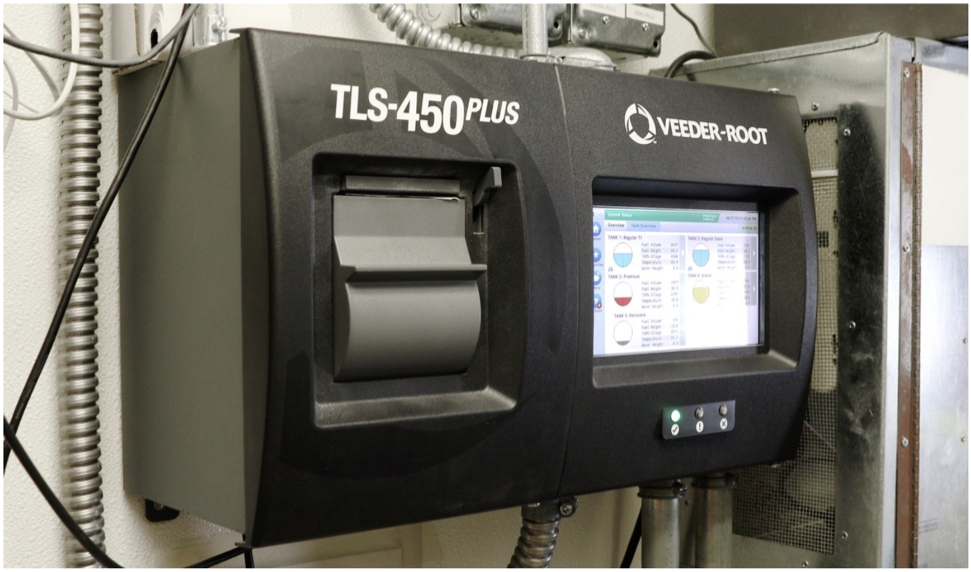
  • Ensure the Reset / Calibration button is held for 10 seconds until the indicator turns red, then release.
    • Controller will automatically run the STP and perform calibration.
  • Ensure solid green indicator and the procedure is complete.
IQ Control Box Calibration

Note 5 – RS-485 COMMUNICATIONS

a. Verify Wiring from IQ Control Box to TLS-450PLUS is in accordance with: Manual 051-330

b. Verify RS-485 Com Module is installed in compatible slots in accordance with: Manual 051-330
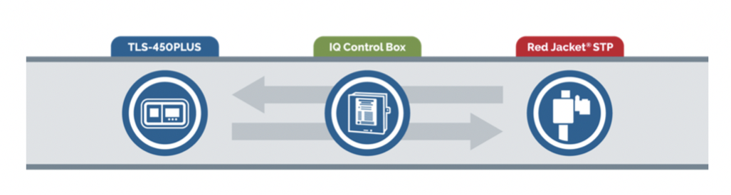
RS-485 Communications

Note 6 – VERIFY TLS-450PLUS / IPC SETUP

a. Verify Communications are programmed.

b. Manual 051-330, Appendix A.

c. Verify proper addressing of pumps in setup on TLS-450PLUS.

d. Verify Dispenser Mode is active and programmed.

e. Auto Event Generation (verifying Switch-on-the-Fly).

f. With a handle signal active, turn off (remove power) from the Primary Pump at the breaker and ensure the Secondary Pump comes on.  

Note 7 – REVIEW ALARM HISTORY FOR IPC

a. Review if IPC Alarm(s) occur.

b. After High Throughput Activity, verify helper condition was activated, use serial command to verify.

Review Alarm History For IPC

Manual Reference Notes 

IQ Control Box Installation and Owner's Manual, 051-330 Rev. K

https://docs.veeder.com/gold/download.cfm?doc_id=9974

  • Table 5 – Motor Type Programming, page 13

  • Table A-2 – Motor Type Programming, page A-6

  • Table 7 – Motor Type Selections, page 15

  • Figure A-5 – SW1 Switch Setup Chart, page A-7


The Red Jacket STP Installation, Service, & Parts Lists Manual,  577013-830 Rev. AC

https://docs.veeder.com/gold/download.cfm?doc_id=7311

Further Information 

Contact Veeder-Root Technical Support at +1.800.323.1799 for additional help or questions.

Related Blogs

footer-logo

Copyright © The Veeder-Root Company.
All rights reserved. Unauthorized duplication prohibited.

125 Powder Forest Drive PO Box 2003
Simsbury, CT 06070

1.800.873.3313   Twitter  LinkedIn  Vimeo  YouTube

Cookie Settings

Trending Blogs
  • Veeder-Root Announces 2024 Circle of Excellence and Distributor of the Year Awards
  • Veeder-Root Unveils the Red Jacket® IQ2 Smart Controller: Revolutionizing Pump Management
  • The Right Configuration for Modern Fuel Management Systems
  • Exciting Updates to THE PLUS VIEW App
  • Expanding Your LLMS Monitoring Applications
  • Understanding Your Risk of Cyber Attacks
  • The 2024 NACS Show – Key Takeaways from This Year’s Event
  • Veeder-Root Expands Portfolio with High-Tech, Retailer-Driven Offerings
Footer Menu
  • Automatic Tank Gauges (ATG)
  • Meter Registers
  • Red Jacket Submersible Pumping Systems (STP)
  • Careers
  • Technical Support
Footer Links
  • Privacy
  • Terms
  • Extranet
  • GDPR Notice