


Fuel Management Solutions for
Retail & Convenience Operators
Increase your profits, detect and reduce fuel loss, and ensure regulatory compliance with the most advanced Automatic Tank Gauge available, the TLS-450PLUS.
Installers & Service Contractors
Need installation support, manuals or assistance specifying the right product for the job? Veeder-Root’s team of product support specialists and technicians are there to help.
Bulk Fuelers
Automate custody transfer transactions at the loading rack, delivery vehicle or anywhere in between to eliminate loss & minimize paperwork with Electronic Meter Registration.
Ready To Upgrade Your Fueling Infrastructure?
Special low-rate financing available exclusively for Veeder-Root TLS-450PLUS Automatic Tank Gauge (ATG) purchases with Patriot Capital. The more units you buy, the more you save.
Start Saving

Veeder-Root Product Guides
Our comprehensive guides highlight our complete product portfolios for Red Jacket®, Commercial & Industrial, and Meter Registration and cover considerations for product selection, ordering, and more.
Explore the guides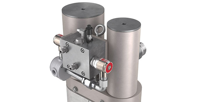
HydrX Fuel Conditioning System
Continuous water removal is the only long-term, sustainable solution for optimal tank health and diesel fuel quality.
Learn More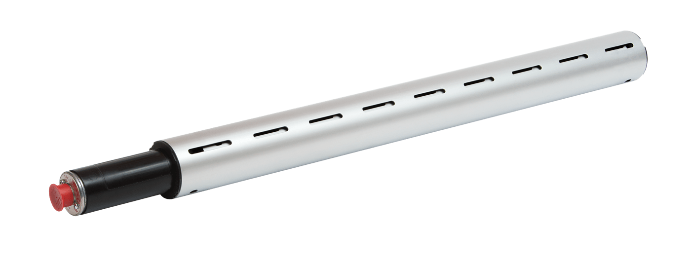
Magnetostrictive Discriminating Dispenser Pan & Containment Sump Sensor
The Veeder-Root Mag Sump Sensor uses proven magnetostrictive technology to detect hydrocarbons or water in sump spaces
Learn More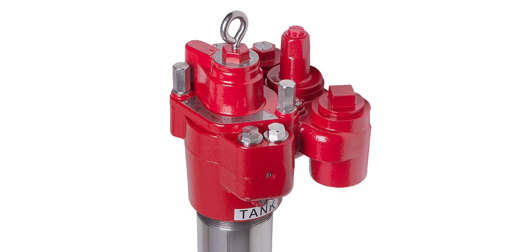
The Red Armor® Submersible Turbine Pump
The ultimate survivor in your fueling infrastructure, the Red Armor series of STPs is built to last in the harshest corrosive environments created by ULSD and ethanol blends.
Learn More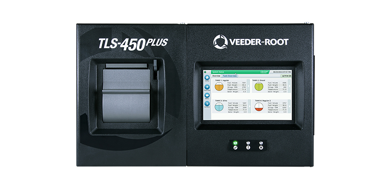
TLS-450PLUS Automatic Tank Gauge
The TLS-450PLUS Automatic Tank Gauge provides the most comprehensive fuel site data for advanced fuel asset management.
Learn More