When a customer activates a dispenser to fuel their vehicle, our Veeder-Root integrated site solutions are working behind-the-scenes to ensure the site’s fueling system is functioning properly and providing the fuel requested. In order to understand how the equipment at a site works together to get fuel from the storage tank into a vehicle’s tank, you first need to know what the key equipment is and its place within the process.
Activating the Dispenser
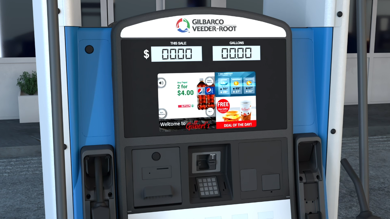
All retail fueling sites need a fuel dispenser, such as a Gilbarco Veeder-Root Encore® 700 S, which has a meter inside it to record how much fuel is dispensed. In some countries the dispenser will also have a pumping unit inside of it, these units use suction to pull the fuel up out of the storage tank and dispense it. In North America, and many other global regions, it’s more common to have a pressurized system, where a submersible turbine pump within the underground storage tank pumps the fuel to the dispenser.
When a customer pulls their vehicle up to the dispenser, they start a transaction, remove the nozzle and select a grade. The dispenser will then request an authorization from the Point-of-Sale System. Nothing will happen until the sales system or cashier gives approval.
Authorization to Dispense
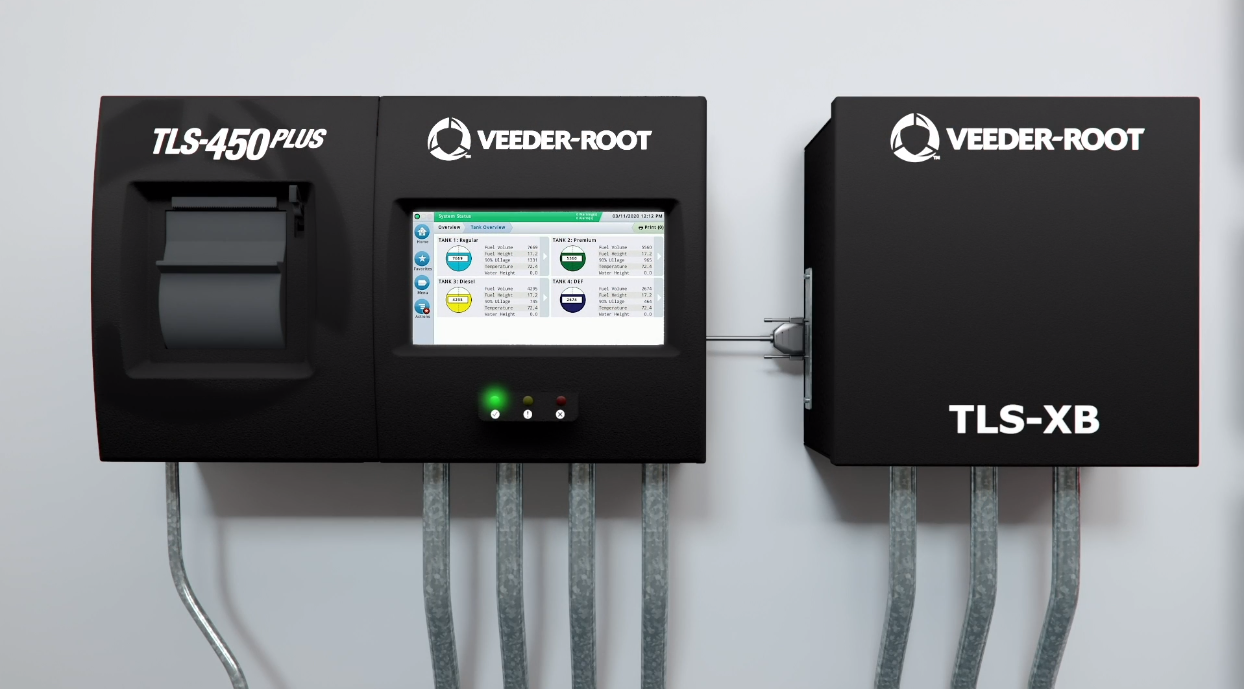
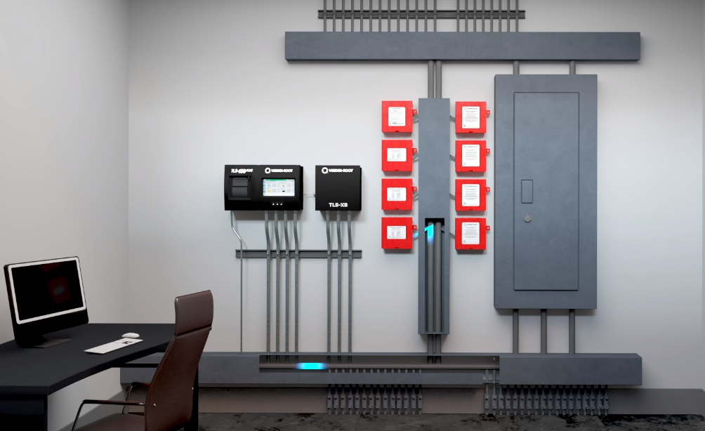
The fuel dispenser maintains connection to three primary pieces of equipment. One is the Red Jacket® ISOTROL™ 1-8 Control Box for the submersible turbine pump, which isolates the handle signals between each dispenser. The dispenser is also connected to the Point-of-Sale System and a TLS-450PLUS Automatic Tank Gauge. These systems manage the transactions, inventory and environmental data.
Once authorized, the dispenser will reset the displays and get ready to dispense fuel. The dispenser signals the ISOTROL 1-8 Control Box, which notifies the TLS-450PLUS ATG. Then, the ATG sends a relay signal to the Red Jacket® IQ Smart Control to start the Red Jacket® Submersible Turbine Pump.
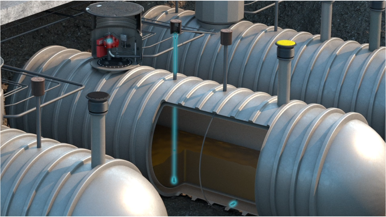
Pumping from the Tank
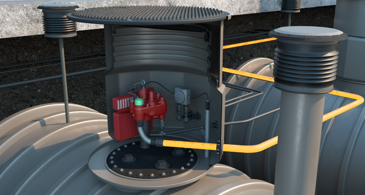
Submersible turbine pumps have two main parts; a packer manifold which is in the sump space and a Unitized Motor Pump (UMP) that sits down in the tank. The packer manifold is designed to flow fuel to the product lines, and contains the electrical connections, capacitors, pressure relief valves, and the leak detector port. The UMP is submerged in fueling product and, once it receives the signal, the motor spins and pumps the fuel up out of the underground storage tank, creating the pressure in the lines.
During dispensing, the dispenser monitors the fuel passing through the meter and updates the sales information on the main display and back to the Point-of-Sale System. When the customer hangs up the nozzle, the dispenser closes its valves, and removes the signal to the ISOTROL 1-8 Control Box, which again signals back through the tank gauge and IQ Smart Control to turn off the STP. Then, it sends a “handle down” signal to the Point-of-Sale System along with the final sales information.
Managing Compliance
Once dispensing is complete, the TLS-450PLUS fuel tank monitoring system will conduct a three gallon per hour line leak test to ensure the integrity of the line, which meets EPA and local fire prevention requirements.
Automatic tank gauging systems consist of sensors and probes connected to a console. The number of devices at the site will depend on the number of tanks and dispensers. If an issue is detected, the TLS-450PLUS ATG will record a condition result and generate an audible and visual alarm for the store operator.
Reconciling Sales
If the retailer is using a tank gauge equipped with Business Inventory Reconciliation then the sales information is compared to the measured fuel volume to verify the sale. Reconciliation reports are then provided on a shift-by-shift basis, providing the retailer with the data they need to meet their regulatory requirements and manage their assets.
Read the Gas Station 101 blog article series for more on the fueling process.